1. Central Processing Unit (CPU) Architecture
Exam Focus:
- Von Neumann vs. Harvard architecture (differences, advantages).
- Roles of registers (MAR, MDR, PC, ACC, CIR, IX).
- Fetch-Execute Cycle (RTN notation, interrupts).
Theory:
- Von Neumann Model: Single bus for data/instructions; bottleneck issue.
- Registers:
- MAR: Holds memory address for read/write.
- MDR: Temporarily stores data fetched from memory.
- PC: Points to next instruction.
- ACC: Stores ALU results.
- Interrupts: Priority handling, ISR (Interrupt Service Routine).
Practice:
- Describe the role of the MAR and MDR during the fetch-execute cycle.
- Memory Address Register (MAR):
- Holds the address of the next instruction or data to be fetched from memory.
- During the fetch stage, the address from the Program Counter (PC) is copied into the MAR.
- Memory Data Register (MDR):
- Temporarily stores the data or instruction fetched from memory.
- After the MAR provides the address, the CPU retrieves the contents of that memory location and stores it in the MDR.
- The instruction/data is then transferred to the Current Instruction Register (CIR) for decoding.
- Memory Address Register (MAR):
- Convert RTN to steps:
MAR ← [PC],MDR ← [[MAR]],CIR ← [MDR].MAR ← [PC]- The address of the next instruction (stored in the PC) is copied into the MAR.
- Example: If
PC = 100, thenMAR = 100.
MDR ← [[MAR]]- The CPU fetches the instruction/data stored at the memory address held in the MAR and loads it into the MDR.
- Example: If memory location
100containsLDM #5, thenMDR = LDM #5.
CIR ← [MDR]- The instruction in the MDR is transferred to the CIR for decoding and execution.
- Example:
CIR = LDM #5.
2. Assembly Language & Addressing Modes
Exam Focus:
- Opcodes (LDM, STO, ADD, JMP).
- Addressing modes (immediate, direct, indirect, indexed).
- Trace tables (common in exams).
Theory:
- Addressing Modes:
- Immediate: Operand = actual data (e.g.,
LDM #5). - Direct: Operand = memory address (e.g.,
LDD 100). - Indexed:
LDX 100uses[100 + IX].
- Immediate: Operand = actual data (e.g.,
- Branching: Conditional (JPE/JPN) vs. unconditional (JMP).
Practice:
- Translate to machine steps:
- LDM #10
- ADD 200
- STO 201
- Answer: Loads 10 in the accumulator, adds data from memory location 200 and stores it into memory location 201.
- Complete a trace table for:
- LDM #3
- STO 100
- INC ACC
- Answer: Loads 3 in the accumulator, stores it in memory location 100(stores 3 in that location). increments accumulator making the acccumulator contents “4”.
3. Bit Manipulation
Exam Focus:
- Logical shifts (LSL/LSR) vs. arithmetic shifts.
- Bit masking (AND/OR/XOR for testing/setting bits).
Theory:
- Shifts:
LSL #2= multiply by 4 (e.g.,00001100→00110000).LSR #1= divide by 2 (e.g.,00001100→00000110).
- Masking:
- Test bit 3:
AND #8(binary00001000). - Set bits 4-7 to 0:
AND #15(binary00001111).
- Test bit 3:
Practice:
- Perform
LSL #3on00010110and state the denary result.- Binary before shift:
00010110(22 in denary). - After
LSL #3:10110000(shift left 3 places, fill with 0s). - Denary result:
10110000= 176.
- Binary before shift:
- Write assembly to test if bit 5 is set in address 300.
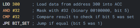
The JPE statement wasn’t needed!
4. System Performance Factors
Exam Focus:
- Clock speed, cache size, cores, bus width.
Theory:
- Clock Speed: Higher = more cycles/second.
- Cache: L1 (fastest), L2, L3 (shared); reduces “wait states.”
- Cores: Parallel processing (multithreading).
Practice:
Explain how increasing cache size improves performance.
Increasing cache size improves performance by reducing the number of cache misses, allowing the CPU to access frequently used data faster. This decreases idle time and increases instruction throughput.
5. Exam-Style Questions
- Short Answer:
- Why does the Von Neumann model use a single bus? What is the drawback?
- *Convert -42 to 8-bit two’s complement.*
- Structured:
- Trace this assembly program
- LDM #5
- ADD #3
- STO 100
- Trace this assembly program
- Essay:
- Compare immediate and indexed addressing, with examples.
6. Practical Applications
- AI in Processors: Predictive caching, branch prediction.
- Embedded Systems: Real-time interrupt handling (e.g., traffic lights).
7. Embedded Systems
Definition:
Specialized computer systems designed to perform dedicated tasks (e.g., traffic lights, washing machines).
Key Features:
- Real-time operation: Must respond to inputs within strict deadlines.
- Limited resources: Small memory, low-power processors.
- Deterministic behavior: Predictable timing for critical tasks.
Examples:
- Medical devices (pacemakers).
- Automotive systems (ABS, airbag control).
- IoT devices (smart thermostats).
8. Interrupt Handling in Embedded Systems
What is an Interrupt?
A signal from hardware/software that pauses the CPU’s current task to handle a high-priority event.
Why Use Interrupts?
- Efficiency: Avoids wasteful polling (e.g., constantly checking if a button is pressed).
- Timeliness: Critical events (e.g., sensor alarms) get immediate attention.
Interrupt Handling Process
- Interrupt Triggered
- Hardware (e.g., timer overflow) or software (e.g., divide-by-zero) sends an interrupt request (IRQ).
- CPU Response
- Finishes current instruction, saves state (registers, PC) to the stack.
- Jump to ISR
- CPU loads the Interrupt Service Routine (ISR) address from the interrupt vector table.
- Execute ISR
- ISR handles the event (e.g., reads sensor data, turns on LED).
- Must be short to avoid delaying other interrupts.
- Return to Main Program
- CPU restores saved state from the stack and resumes where it left off.
Types of Interrupts
- Hardware Interrupts
- External (e.g., button press, UART data received).
- Internal (e.g., timer overflow, ADC conversion complete).
- Software Interrupts
- Triggered by instructions (e.g.,
SWIin ARM). - Used for system calls (e.g., OS tasks).
- Triggered by instructions (e.g.,